Beechcraft King Air 350i Startup Checklist
Beechcraft King Air 350i Startup Notes
The 350i is a lesson in PT6 discipline. Everything runs through the condition levers: they sit at fuel cutoff for the start, and the moment you lift one to low idle you are committed to fuel and ignition. Engage the starter, wait for N1 to spin up and stabilize, at 12 percent minimum, then bring the condition lever up while watching ITT climb. The second engine is normally a generator-assisted cross start, and the autofeather system gets its own dedicated test at runup.
Hot starts are the big trap. Lifting the condition lever before N1 stabilizes means fuel pooling in a slow-turning engine and an ITT that rockets toward the limit; if it runs away, cut the fuel and keep motoring. Impatience causes the second classic error: cross-starting engine two before the first generator's load has dropped enough to support it. And plenty of sim pilots skip the autofeather test entirely, which on this airplane is a real checklist item, not decoration.
Common mistakes
- Raising the condition lever before N1 stabilizes at 12 percent
- Cross-starting the second engine before generator load drops
- Skipping the autofeather test at runup
Related Aircraft
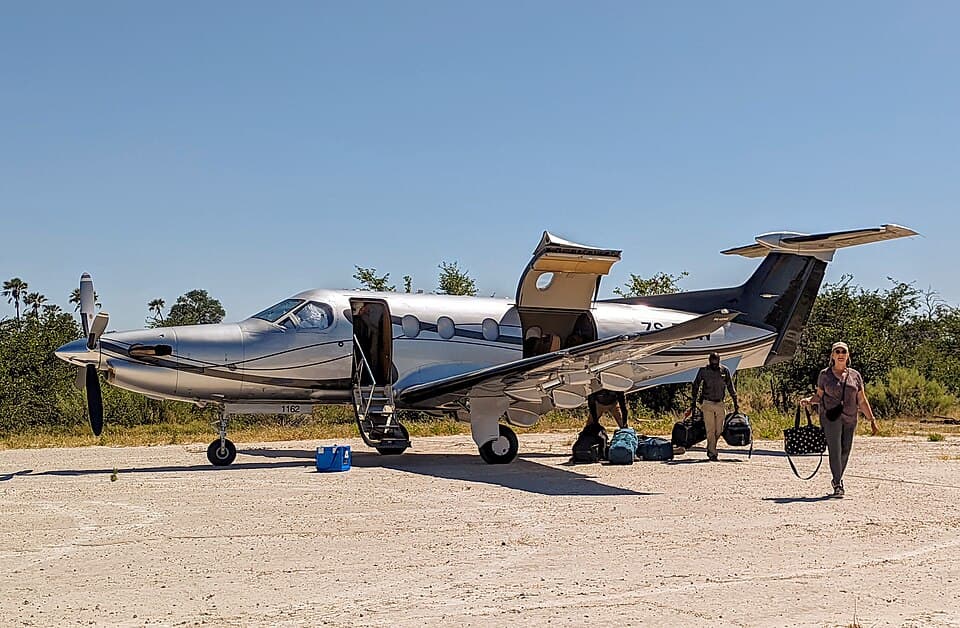
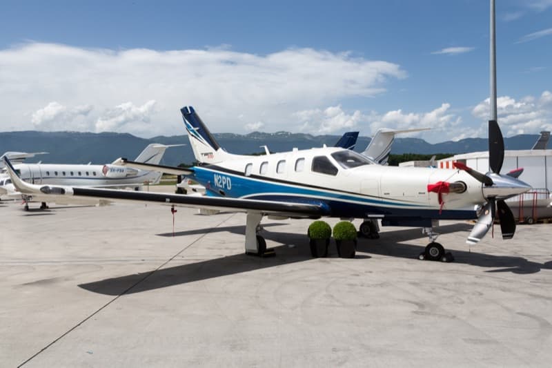
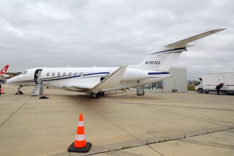
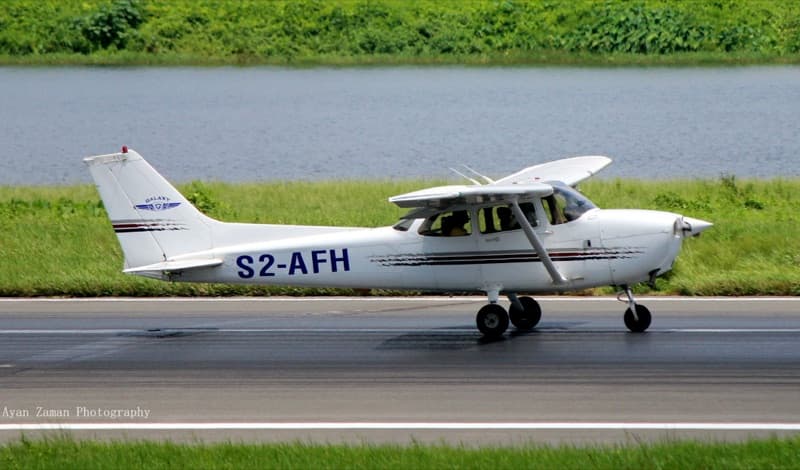
| 01 | Weather Briefing (METAR / TAF)REVIEWED | |
| 02 | NOTAMsREVIEWED | |
| 03 | Fuel RequiredCALCULATEDCAUTION: Aviation gasoline is an emergency fuel only: limited to 150 hours between engine overhauls, prohibited if either standby fuel pump is inoperative, and crossfeed is required above FL200.NOTE: Approved commercial fuels: Jet A, Jet A-1, Jet B, Chinese No. 3. Military: JP-4, JP-5, JP-8. | |
| 04 | Weight, CG, Performance and V-SpeedsCHECKEDNOTE: Checklist airspeeds are quoted at 15,000 lb (6804 kg). | |
| 05 | Takeoff PerformanceCALCULATEDNOTE: V1, VR, V2 and static takeoff power are confirmed again in the Before Takeoff (Runup) checklist. | |
| 06 | Route / Flight PlanPREPARED AND LOADED | |
| 07 | ATISOBTAINED | |
| 08 | Anti-Icing Additive (if used)BLENDED 0.10 TO 0.15% BY VOLUMECAUTION: Improper concentration causes deterioration of the fuel cell sealant.NOTE: Additive conforming to MIL-I-27686 or MIL-I-85470. Check with the fuel supplier whether additive has already been added. |
| 01 | Monogram Electric Toilet Knife Valve (if installed)OPEN | |
| 02 | BaggageSECURE | |
| 03 | Aft Exit SignON-TESTNOTE: Check sign illumination, then OFF-RESET. | |
| 04 | Forward Exit SignON-TESTNOTE: Check sign illumination, then OFF-RESET. | |
| 05 | Emergency ExitsSECURE AND UNLOCKED | |
| 06 | Control LocksREMOVE | |
| 07 | Parking BrakeSET | |
| 08 | Landing Gear ControlDOWN | |
| 09 | ELT (cockpit installations)ARM | |
| 10 | Condition LeversFUEL CUTOFF | |
| 11 | Elevator TrimSET TO 2 UNITS NOSE UP | |
| 12 | Rudder and Aileron TrimSET TO 0 UNITS | |
| 13 | Battery BusNORM | |
| 14 | Voltmeter - BAT Position23 VOLTS MINIMUMNOTE: All other positions 0 volts. | |
| 15 | BatteryON | |
| 16 | Landing Gear LightsL, R AND NOSE ILLUMINATED | |
| 17 | Fuel QuantityCHECK MAIN AND AUXILIARY | |
| 18 | Voltmeter - TPL FED22 VOLTS MINIMUMNOTE: R GEN and L GEN 0 volts, CTR 23 volts minimum, EXT PWR 0 volts. | |
| 19 | Gen TiesMAN CLOSE | |
| 20 | Voltmeter - R GEN and L GEN23 VOLTS MINIMUM | |
| 21 | Flaps (if desired)CHECKNOTE: Move to and verify they stop at TAKEOFF AND APPROACH, then at DOWN. | |
| 22 | Airstair Door CircuitryCHECK | |
| 23 | BatteryOFF | |
| 24 | Oxygen System Preflight InspectionCOMPLETE |
| 01 | Cabin Door Seal, Step Extension Cable, Light Wire, Damper and HandrailsCHECK | |
| 02 | Left Side WindowsCHECK | |
| 03 | Flaps (condition, asymmetry protection, flap tracks)CHECK | |
| 04 | Aileron and TabCHECK | |
| 05 | Static Wicks (aileron and winglet)CHECK | |
| 06 | Siphon Break VentCLEAR | |
| 07 | LightsCHECK | |
| 08 | Main Fuel Tank CapSECURE | |
| 09 | Stall Warning VaneCHECK | |
| 10 | Tie-DownREMOVE | |
| 11 | Flush Outboard Fuel DrainDRAIN | |
| 12 | Outboard Deice Boot and Stall StripCHECK | |
| 13 | Leading-Edge Fuel Tank and Gravity-Line DrainsDRAIN | |
| 14 | Inverter Cooling LouversCLEAR | |
| 15 | Flush Fuel Vent and Heated Fuel VentCLEAR | |
| 16 | Landing Gear (doors, tires, strut, wheel well)CHECK | |
| 17 | Engine Oil VentCLEAR | |
| 18 | Brake Line and Brake Deice Plumbing (if installed)CHECK | |
| 19 | Torque Knee Assembly and Safety SwitchCHECK | |
| 20 | BrakesCHECK | |
| 21 | Fire Extinguisher PressureCHECKNOTE: Pressure varies with temperature, for example 340 to 420 psi at 40 degF (4 degC) and 455 to 550 psi at 80 degF (27 degC). | |
| 22 | ChocksREMOVE | |
| 23 | Fuel Strainer and Fuel Filter DrainsDRAIN | |
| 24 | Ice Vane and Oil Radiator ExhaustCLEAR | |
| 25 | Engine OilCHECK QUANTITY, CAP SECURE | |
| 26 | Engine Cowling, Doors and PanelsSECURE | |
| 27 | Exhaust Stack and FairingCHECK FOR CRACKS | |
| 28 | PropellerCHECK AND ROTATE | |
| 29 | Engine and Oil Radiator Air IntakesCHECK | |
| 30 | Auxiliary Fuel Tank CapSECURE | |
| 31 | Inboard Deice BootCHECK | |
| 32 | Auxiliary Fuel Tank DrainDRAIN |
| 01 | OAT Probe / Relief Tube VentCHECK | |
| 02 | Brake Reservoir VentCLEAR | |
| 03 | Left Avionics Access PanelSECURE | |
| 04 | Air Conditioner Condenser Exhaust DuctCLEAR | |
| 05 | Windshield and WipersCHECK | |
| 06 | Radome ConditionCHECK | |
| 07 | Pitot MastsCLEAR | |
| 08 | Landing and Taxi LightsCHECK | |
| 09 | Nose Gear (shimmy damper, stop block, torque knee, strut, tire)CHECK | |
| 10 | ChocksREMOVE | |
| 11 | Nose Gear Doors and Wheel WellCHECK | |
| 12 | Air Conditioner Condenser Intake DuctCLEAR | |
| 13 | Right Avionics Access PanelSECURE |
| 01 | Ejector ExhaustCLEAR | |
| 02 | Auxiliary Fuel Tank DrainDRAIN | |
| 03 | Battery Box DrainCLEAR | |
| 04 | Lower PanelsSECURE | |
| 05 | Heat Exchanger Air Intake and ExhaustCLEAR | |
| 06 | Inboard Deice BootCHECK | |
| 07 | Battery Access PanelSECURE | |
| 08 | Auxiliary Fuel Tank CapSECURE | |
| 09 | Engine OilCHECK QUANTITY, CAP SECURE | |
| 10 | Engine Cowling, Doors and PanelsSECURE | |
| 11 | Collector DrainCLEAR | |
| 12 | Exhaust Stack and FairingCHECK FOR CRACKS | |
| 13 | PropellerCHECK AND ROTATE | |
| 14 | Engine and Oil Radiator Air IntakesCHECK | |
| 15 | Generator Air IntakeCLEAR | |
| 16 | Ice LightCHECK | |
| 17 | Fuel Filter and Fuel Strainer DrainsDRAIN | |
| 18 | Landing Gear (doors, tires, strut, wheel well)CHECK | |
| 19 | Fire Extinguisher PressureCHECK | |
| 20 | BrakesCHECK | |
| 21 | ChocksREMOVE | |
| 22 | Heated Fuel Vent and Flush Fuel VentCLEAR | |
| 23 | Gravity-Line and Leading-Edge Fuel Tank DrainsDRAIN | |
| 24 | External Power DoorSECURE | |
| 25 | Outboard Deice Boot and Stall StripCHECK | |
| 26 | Tie-DownREMOVE | |
| 27 | Flush Outboard Fuel DrainDRAIN | |
| 28 | Main Fuel Tank CapSECURE | |
| 29 | Static Wicks (winglet and aileron)CHECK | |
| 30 | AileronCHECK | |
| 31 | FlapsCHECK |
| 01 | Lower Antennas and BeaconCHECK | |
| 02 | Oxygen Service Access DoorSECURE | |
| 03 | Static Ports (right)CLEAR | |
| 04 | ELT (aft fuselage installations)AUTO | |
| 05 | ELT AntennaCHECK | |
| 06 | Aft Compartment Bottom Access DoorSECURE | |
| 07 | Tie-DownREMOVE | |
| 08 | Ventral Fin Drain HolesCLEAR | |
| 09 | Cabin Air ExhaustCLEAR | |
| 10 | Ventral Fin and Static WickCHECK | |
| 11 | VOR Antennas (right and left)CHECK | |
| 12 | Rudder, Rudder Tab, Stinger and Static WicksCHECK | |
| 13 | Horizontal Stabilizer, Boots and Static WicksCHECK | |
| 14 | Elevator, Tab and Static WicksCHECK | |
| 15 | Tabs In Neutral PositionVERIFY | |
| 16 | Position Light and Tail FloodlightsCHECK | |
| 17 | Access Panels (left)SECURE | |
| 18 | Static Ports (left)CLEAR | |
| 19 | Oxygen Overpressure Discharge and Aft Compartment Drain TubesCLEAR | |
| 20 | Relief TubeCLEAR |
| 01 | Weight, CG, Performance and V-SpeedsCHECKED | |
| 02 | Airstair DoorLOCKEDWARNING: Only a crew member or properly trained ground personnel should close and lock the airstair door and cargo door. | |
| 03 | Cargo Door (B300C)LOCKED | |
| 04 | Load and BaggageCONFIRM SECURED | |
| 05 | Passenger BriefingCOMPLETE | |
| 06 | Seats and TablesPOSITIONEDNOTE: All seat backs upright, headrests fully extended, lateral-tracking seats outboard, tables stowed. | |
| 07 | Pilot Seats and Rudder PedalsADJUSTED | |
| 08 | Seat Belts and Shoulder HarnessesFASTENED | |
| 09 | Parking BrakeCONFIRM SET | |
| 10 | Control LocksCONFIRM REMOVED | |
| 11 | Oxygen System Preflight InspectionCONFIRM COMPLETE | |
| 12 | Fuel PanelCHECKNOTE: Standby pumps OFF, crossfeed OFF, aux transfer switches AUTO, circuit breakers IN. | |
| 13 | Pilot's GyroSLAVED (OUT) | |
| 14 | Standby Horizon (if installed)TEST | |
| 15 | Battery BusCONFIRM NORM | |
| 16 | Engine Anti-IceON AND MAIN | |
| 17 | Landing Gear Relay Circuit BreakerIN | |
| 18 | Landing Gear ControlDOWN | |
| 19 | Power LeversIDLE | |
| 20 | Prop LeversFULL FORWARD | |
| 21 | Condition LeversFUEL CUTOFF | |
| 22 | Oxygen ControlsPASSENGER MANUAL DROP-OUT PUSHED OFF / SYSTEM READY ON | |
| 23 | EFIS Power (if installed)OFF | |
| 24 | Landing Gear Alternate Extension HandleSTOWED | |
| 25 | Copilot's SubpanelCHECKNOTE: Window defog OFF, vent blower AUTO, cabin temp mode OFF, environmental bleed air LOW, bleed air valves ENVIR OFF, aft blower OFF, electric heat OFF. | |
| 26 | Copilot's GyroSLAVED (OUT) | |
| 27 | Right Panel Circuit BreakersIN | |
| 28 | Pilot's Static Air SourceNORMAL | |
| 29 | BatteryON | |
| 30 | AnnunciatorsTEST | |
| 31 | Fuel Quantity (main and auxiliary)CHECK | |
| 32 | Landing Gear Control LightsTEST | |
| 33 | Hydraulic Fluid SensorTESTNOTE: HYD FLUID LO annunciator illuminated. | |
| 34 | BeaconON | |
| 35 | Cabin Altitude WarningTESTNOTE: CABIN ALT HI and CABIN ALTITUDE illuminated, note aural warning. | |
| 36 | Cabin Differential WarningTESTNOTE: CABIN DIFF HI illuminated. | |
| 37 | Overspeed WarningTESTNOTE: Note aural warning. | |
| 38 | Stall and Landing Gear WarningTESTNOTE: Note aural warning. | |
| 39 | Fire Detector and ExtinguisherTESTNOTE: Left and right ENG FIRE illuminated; left and right EXTINGUISHER PUSH and DISCHARGED illuminated. |
| 01 | Gen Ties (for night operation)MAN CLOSE | |
| 02 | Propeller AreaCLEAR | |
| 03 | Right Ignition and Engine StartONCAUTION: Starter use is limited to 30 seconds ON, 5 minutes OFF, 30 seconds ON, 5 minutes OFF, 30 seconds ON, then 30 minutes OFF.NOTE: R IGNITION ON illuminated, R FUEL PRES LO extinguished. | |
| 04 | Right Condition Lever (after 12% N1 minimum)LOW IDLEWARNING: Do not introduce fuel below 12% N1. | |
| 05 | Right ITT and N1MONITORWARNING: Maximum starting ITT is 1000 degC, time limited to 5 seconds. | |
| 06 | Right Oil PressureCHECKNOTE: Starting oil pressure range 0 to 200 psi; minimum oil temperature -40 degC. | |
| 07 | Right Ignition and Engine Start (at 50% N1 or above)OFF | |
| 08 | Right Condition LeverHIGH IDLENOTE: High idle limits power operation to a minimum of 70% N1; low idle to a minimum of 62% N1. | |
| 09 | Right GeneratorRESET, THEN ONNOTE: R DC GEN, L GEN TIE OPEN and R GEN TIE OPEN extinguished. | |
| 10 | BatteryCHARGENOTE: Until the loadmeter reads approximately 50% or less. | |
| 11 | Left Ignition and Engine StartONNOTE: L IGNITION ON illuminated, L FUEL PRES LO extinguished. | |
| 12 | Left Condition Lever (after 12% N1 minimum)LOW IDLE | |
| 13 | Left ITT and N1MONITORWARNING: Maximum starting ITT is 1000 degC, time limited to 5 seconds. | |
| 14 | Left Oil PressureCHECK | |
| 15 | Left Ignition and Engine Start (at 50% N1 or above)OFF | |
| 16 | Right Condition LeverREDUCE TO LOW IDLE | |
| 17 | Left and Right Prop RPM1050 MINIMUMNOTE: Minimum idle prop speed limit is 1050 RPM. | |
| 18 | L PROP PITCH and R PROP PITCHILLUMINATED | |
| 19 | VoltmeterL GEN - 27.5 TO 29.0 VOLTS | |
| 20 | Left GeneratorRESET, THEN ONNOTE: L DC GEN extinguished. | |
| 21 | Right GeneratorRESET, THEN ONNOTE: L GEN TIE OPEN and R GEN TIE OPEN remain extinguished with the switch in the RESET position. | |
| 22 | Hot Start or Hung StartCONDITION LEVER FUEL CUTOFFWARNING: Condition lever FUEL CUTOFF, ignition and engine start to STARTER ONLY, and at ITT below 400 degC set IGNITION AND ENGINE START OFF. Do not attempt another start until the cause has been corrected. | |
| 23 | No Light StartCONDITION LEVER FUEL CUTOFFWARNING: If no ITT rise is observed within 10 seconds after moving the condition lever to LOW IDLE: condition lever FUEL CUTOFF, ignition and engine start OFF, allow 5 minutes for fuel to drain and the starter to cool, then perform Engine Clearing. | |
| 24 | Engine ClearingSTARTER ONLY FOR MAX 30 SECONDSNOTE: Condition lever FUEL CUTOFF, ignition and engine start STARTER ONLY for a maximum of 30 seconds, then OFF. Allow 5 minutes before another start attempt. |
| 01 | Electrical SystemCHECK | |
| 02 | InvertersCHECK AND ON | |
| 03 | Avionics MasterON | |
| 04 | Master Panel and Cockpit LightsAS REQUIRED | |
| 05 | Mic SwitchesNORMAL | |
| 06 | Cabin LightsAS REQUIRED | |
| 07 | FurnishingsAS REQUIRED | |
| 08 | Cabin SignNO SMK/FSB OR FSB | |
| 09 | Standby Horizon (if installed)ON | |
| 10 | Prop SyncON | |
| 11 | Exterior LightsAS REQUIRED | |
| 12 | EFIS Power (if installed)ON | |
| 13 | Environmental System ControlsSET | |
| 14 | AltimetersSET | |
| 15 | Standby Horizon (if installed)UNCAGE | |
| 16 | FlapsUP | |
| 17 | Flight ControlsCHECK FOR FULL FREEDOM OF MOVEMENT AND PROPER DIRECTION OF TRAVEL | |
| 18 | BrakesRELEASE AND CHECK |
| 01 | Avionics and RadarCHECK | |
| 02 | PressurizationCHECK AS REQUIRED AND SET | |
| 03 | AutopilotCHECK | |
| 04 | Yaw DampCHECK | |
| 05 | Electric Pitch TrimCHECK | |
| 06 | Trim TabsSET | |
| 07 | Engine Controls Friction LocksSET | |
| 08 | FlapsCHECK AND SET | |
| 09 | Overspeed Governors and Rudder BoostCHECK | |
| 10 | Low Pitch Stops and Primary GovernorsCHECK | |
| 11 | AutofeatherCHECK | |
| 12 | AutofeatherARMNOTE: AUTOFTHER OFF extinguished. | |
| 13 | Manual Propeller FeatheringCHECK | |
| 14 | Instrument Vacuum and Deice PressureCHECK | |
| 15 | Engine Anti-IceCHECK | |
| 16 | Ice Protection Equipment (if required)CHECK | |
| 17 | Fuel Quantity, Flight and Engine InstrumentsCHECK | |
| 18 | V1, VR, V2 and Static Takeoff PowerCONFIRM |
| 01 | Engine Auto IgnitionARM (IF REQUIRED)NOTE: L IGNITION ON and R IGNITION ON illuminated if armed. | |
| 02 | Engine Anti-IceAS REQUIRED | |
| 03 | Exterior LightsAS REQUIRED | |
| 04 | Windshield Anti-IceNORMAL/HI (IF REQUIRED) | |
| 05 | Prop DeiceAUTO (IF REQUIRED) | |
| 06 | Left and Right Fuel Vent HeatON | |
| 07 | Stall Warning HeatON | |
| 08 | Left and Right Pitot HeatON | |
| 09 | TransponderALT | |
| 10 | Prop LeversCONFIRM FULL FORWARD | |
| 11 | TrimCONFIRM SET | |
| 12 | FlapsCONFIRM SET | |
| 13 | Environmental Bleed AirLOW ABOVE 10 DEGC / NORMAL AT OR BELOW 10 DEGC | |
| 14 | Bleed Air ValvesAS REQUIRED | |
| 15 | Electric HeatOFFNOTE: ELEC HEAT ON extinguished. | |
| 16 | Aft BlowerAS REQUIRED | |
| 17 | Interior LightsAS REQUIRED | |
| 18 | Generator LoadCHECKCAUTION: Ground generator load limit is 75% between 62% and 70% N1, and 100% between 70% and 100% N1.NOTE: When OAT is greater than 10 degC: with A/C ON loadmeters must be 30% or less; with A/C OFF 50% or less. | |
| 19 | Battery AmmeterCHECKNOTE: Charge current 10 amps or less if required. Applies to airplanes FL-215 thru FL-382 except FL-381, FM-10 and FM-11. | |
| 20 | AnnunciatorsOFF OR CONSIDERED |
| 01 | BrakesHOLDWARNING: Do not cycle boots during takeoff. | |
| 02 | Power LeversSET STATIC TAKEOFF POWERWARNING: Takeoff limits: torque 100%, ITT 820 degC, N1 104%, prop 1700 RPM, oil pressure 90 to 135 psi, oil temperature 0 to 110 degC.CAUTION: Torque excursions up to 102% are time limited to 7 minutes; propeller excursions up to 1735 RPM are time limited to 7 minutes. | |
| 03 | Autofeather AnnunciatorsILLUMINATED | |
| 04 | BrakesRELEASE | |
| 05 | VRROTATE TO APPROXIMATELY 10 DEG | |
| 06 | Landing Gear (positive climb established)UP | |
| 07 | AirspeedMAINTAIN V35 UNTIL CLEAR OF OBSTACLES | |
| 08 | Flaps (at 125 knots minimum)UP | |
| 09 | Rolling Takeoff VariantPOWER SET WITHIN 10 SECONDS OF BRAKE RELEASENOTE: For a rolling takeoff, release brakes first and set static takeoff power within 10 seconds of brake release, observing ITT limits. |
| 01 | Bleed Air ValvesOPEN | |
| 02 | Environmental Bleed AirAS REQUIRED | |
| 03 | Yaw DampON | |
| 04 | Climb PowerSETWARNING: Cruise climb ITT limit is 785 degC, which is lower than the maximum cruise limit. | |
| 05 | Props1600 RPM, OR AS DESIRED | |
| 06 | Windshield Anti-IceNORMAL | |
| 07 | Engine InstrumentsMONITOR | |
| 08 | Cabin SignAS REQUIRED | |
| 09 | PressurizationCHECK | |
| 10 | LightsAS REQUIRED | |
| 11 | Climb Speed ReferenceVX 125 KIAS / VY 140 KIASNOTE: Cruise climb: 170 kt to 10,000 ft, 160 kt to 15,000 ft, 150 kt to 20,000 ft, 140 kt to 25,000 ft, 130 kt to 30,000 ft, 120 kt to 35,000 ft. |
| 01 | Cruise PowerSET PER CRUISE POWER TABLES OR GRAPHSWARNING: Do not lift the power levers in flight.NOTE: Maximum cruise ITT limit 820 degC; maximum continuous 820 degC. N1 maximum 104%, prop 1700 RPM. | |
| 02 | AutofeatherOFF | |
| 03 | Aft BlowerAS REQUIRED | |
| 04 | Engine InstrumentsMONITOR | |
| 05 | Fuel GagesMONITORNOTE: Ensure that fuel is being transferred from the auxiliary tanks. | |
| 06 | Engine Ice ProtectionON IN VISIBLE MOISTURE AT +5 DEGC AND BELOWWARNING: If in doubt, actuate the engine anti-ice system. Engine icing can occur even though no surface icing is present.NOTE: Check for proper operation by noting the torque drop. L ENG ANTI-ICE and R ENG ANTI-ICE illuminated. | |
| 07 | Engine Auto-IgnitionARM | |
| 08 | Prop DeiceAUTONOTE: Relieve propeller imbalance due to ice by increasing RPM briefly and returning to the desired setting. | |
| 09 | Surface Deice (ice accumulation 1/2 to 1 inch)SINGLE AND RELEASEWARNING: An accumulation of one inch of ice on the leading edges can cause a 500 FPM loss of climb rate, up to 75 knots TAS cruise speed reduction and up to 15 knots IAS stall speed increase. Maintain a minimum of 140 knots in sustained icing.NOTE: Pneumatic pressure gage should indicate 12.0 to 20.0 psi before boots are activated. WING DEICE illuminates within 6 seconds and TAIL DEICE within 10 seconds in SINGLE mode. | |
| 10 | Windshield Anti-IceNORMAL/HICAUTION: Maximum airspeed for effective windshield anti-icing is 226 knots. In the event of windshield icing, reduce airspeed to 226 knots or below. | |
| 11 | Left and Right Fuel Vent HeatON | |
| 12 | Left and Right Pitot HeatON | |
| 13 | Stall Warn HeatON | |
| 14 | Wing Ice LightsAS REQUIRED |
| 01 | Pressurization - Cabin AltitudeSET | |
| 02 | Pressurization - Rate ControlAS DESIRED | |
| 03 | AltimeterSET | |
| 04 | Cabin SignAS REQUIRED | |
| 05 | Windshield Anti-IceAS REQUIRED | |
| 06 | Windshield DefrostAS REQUIRED | |
| 07 | Window DefogAS REQUIRED | |
| 08 | Fuel BalanceCHECK | |
| 09 | Seats and TablesPOSITIONEDNOTE: All seat backs upright, headrests fully extended, lateral-tracking seats outboard, tables stowed. |
| 01 | Approach SpeedsCONFIRMNOTE: VREF at 15,000 lb (6804 kg) is 109 kt; 14,000 lb 105 kt; 13,000 lb 102 kt; 12,000 lb 100 kt; 11,000 and 10,000 lb 100 kt. Approach climb is VREF + 10 knots; balked landing is VREF. | |
| 02 | AutofeatherARM | |
| 03 | Environmental Bleed AirLOW | |
| 04 | Cabin SignNO SMK/FSB OR FSB | |
| 05 | FlapsAPPROACHCAUTION: Maximum speed with flaps in approach position is 202 KIAS. | |
| 06 | Landing GearDOWN | |
| 07 | Exterior and Interior LightsAS REQUIRED | |
| 08 | RadarAS REQUIRED | |
| 09 | Surface DeiceAS REQUIREDNOTE: Prior to a landing approach, cycle the deicing boots to shed any accumulated ice. |
| 01 | FlapsDOWNCAUTION: Maximum speed permissible with flaps extended beyond approach is 158 KIAS. | |
| 02 | AirspeedVREF | |
| 03 | Yaw DampOFF | |
| 04 | Power LeversIDLE | |
| 05 | Prop LeversFULL FORWARD | |
| 06 | Power Levers (after touchdown)LIFT AND SELECT GROUND FINE | |
| 07 | BrakesAS REQUIRED | |
| 08 | Maximum Reverse Thrust Landing VariantCONDITION LEVERS HIGH IDLECAUTION: Max reverse limits: ITT 760 degC, prop 1650 RPM, oil temperature 0 to 99 degC.NOTE: For a maximum reverse thrust landing set condition levers HIGH IDLE before landing, then after touchdown lift the power levers through ground fine and into reverse, brakes as required, and return the condition levers to LOW IDLE. | |
| 09 | Balked LandingMAXIMUM ALLOWABLE POWER / MAINTAIN VREFNOTE: Balked landing: power maximum allowable, maintain VREF, flaps APPROACH at VREF + 10 knots, landing gear UP with positive climb, flaps UP at 125 knots minimum. |
| 01 | Engine Auto-IgnitionOFF | |
| 02 | Engine Anti-IceON | |
| 03 | LightsAS REQUIRED | |
| 04 | Ice ProtectionOFF | |
| 05 | TransponderSTANDBY | |
| 06 | RadarSTANDBY OR OFF | |
| 07 | TrimSET | |
| 08 | FlapsUP | |
| 09 | Pressurization DifferentialVERIFY 0 | |
| 10 | Bleed Air ValvesENVIR OFF |
| 01 | Parking BrakeSET | |
| 02 | Electric HeatOFF | |
| 03 | EFIS Power (if installed)OFF | |
| 04 | Standby Horizon (if installed)CAGED AND OFF | |
| 05 | Avionics MasterOFF | |
| 06 | InvertersOFF | |
| 07 | AutofeatherOFF | |
| 08 | Exterior LightsOFF | |
| 09 | Vent BlowerAUTO | |
| 10 | Cabin Temp ModeOFF | |
| 11 | Aft BlowerOFF | |
| 12 | Aft HeatAS DESIRED | |
| 13 | Oxygen ControlsPUSH OFF | |
| 14 | BatteryCHARGED | |
| 15 | Brake Deice (if installed, last flight of the day)ON, THEN OFFCAUTION: The brake deice system is not to be continuously operated above 15 degC ambient temperature. | |
| 16 | ITTSTABILIZED AT MINIMUM OBTAINABLE TEMPERATURE FOR ONE MINUTE | |
| 17 | Instrument Emergency LightsON IF DESIRED FOR A NIGHT SHUTDOWN | |
| 18 | Condition LeversFUEL CUTOFF | |
| 19 | Prop LeversFEATHER | |
| 20 | Overhead Panel SwitchesOFF | |
| 21 | Battery and Generator Switches (below 15% N1)OFF | |
| 22 | Control LocksINSTALL | |
| 23 | Instrument Emergency LightsOFF | |
| 24 | Tie-Downs and ChocksINSTALL | |
| 25 | External CoversINSTALL | |
| 26 | Parking BrakeOFF | |
| 27 | Baggage Compartment LightsOFF | |
| 28 | Cabin Entry LightsOFF |