ATR 72-600MSFS 2024 Startup Checklist · 123 steps
ATR 72-600
MSFS 2024 - 0/123 STEPS
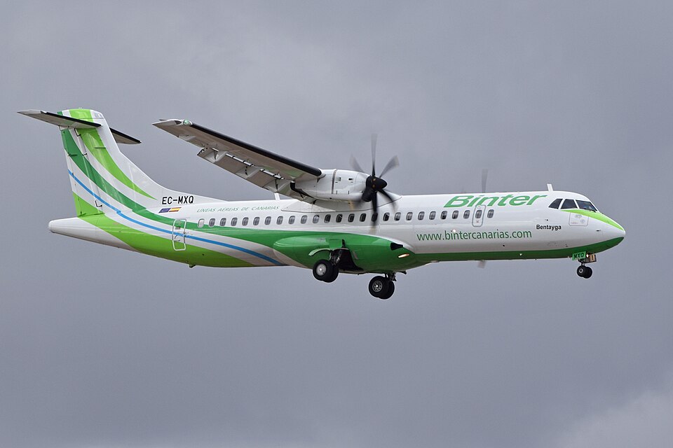
Wikimedia CommonsCC BY-SA 4.0
AirlinerModern
AIRCRAFT BRIEF
The ATR 72-600 is the latest and most capable variant of the ATR 72 family, the world's best-selling regional turboprop. Developed jointly by Airbus and Leonardo (formerly Alenia Aeronautica) in Toulouse, it entered service in 2009 with Finnair. Powered by twin Pratt and Whitney Canada PW127M engines and featuring the advanced ATR Avionics Suite (AAS) with five large LCD displays, the 72-600 carries up to 70 passengers over regional routes with exceptional fuel efficiency. The ATR family has achieved over 200 million flight hours worldwide.
RANGE VISUALIZER
SPECIFICATIONS
manufacturerATR (Airbus / Leonardo)
first Flight2009
roleRegional turboprop airliner
crew2 pilots + cabin crew
engines2x Pratt and Whitney Canada PW127M (2,475 shp each)
max Speed510 km/h (275 kts)
range1,528 km (825 nmi)
ceiling25,000 ft
weight22,800 kg (MTOW)
PHS 1 — Pre-Flight Planning8 steps
| 01 | Weather Briefing (METAR / TAF)NOTE: Check current conditions and forecast at departure, enroute, and destination airports. ATR 72 is not approved for flight into known severe icing. | REVIEWED | |
| 02 | NOTAMsNOTE: Check for runway closures, nav-aid outages, and airspace restrictions along route. | REVIEWED | |
| 03 | Fuel RequiredNOTE: Typical burn ~1,200 kg/hr per engine. Plan for trip fuel + alternate + 45-minute reserve. | CALCULATED | |
| 04 | Weight & BalanceCAUTION: Max takeoff weight 22,800 kg. Max landing weight 22,350 kg. Verify CG within envelope. | WITHIN LIMITS | |
| 05 | Takeoff & Landing PerformanceNOTE: Account for elevation, temperature, and wind. ATR is optimized for short regional runways. | CALCULATED | |
| 06 | OFP / Flight PlanNOTE: Verify route, alternates, RVSM requirements, and step climb plan in FMS. | REVIEWED & LOADED | |
| 07 | ATIS / D-ATISNOTE: Record active runway, wind, QNH, and temperature. | OBTAINED | |
| 08 | GSX - Fuel TruckNOTE: GSX menu: Refuel Aircraft. Verify fuel load matches OFP fuel requirement. | REFUEL COMPLETE |
PHS 2 — Cockpit Preparation14 steps
| 01 | Battery 1 / Battery 2WARNING: Do not start ground power or APU before batteries are confirmed ON. | ON | |
| 02 | Emergency Exit Lights | ARM | |
| 03 | External Power (GPU)NOTE: Use GPU before APU start to preserve fuel. | CONNECTED / ON | |
| 04 | Overhead PanelNOTE: Verify all lights extinguished except those normally illuminated. | CHECKED | |
| 05 | Avionics / ADIRUNOTE: Allow full 10-minute alignment if cold. Do not taxi during alignment. | ON - ALIGNING | |
| 06 | Standby Instruments | CHECKED | |
| 07 | Radios & FrequenciesNOTE: Pre-set departure ATIS, ground, and tower frequencies. | SET | |
| 08 | FMS / FMC RouteNOTE: Enter route, SID, cruise altitude, and fuel data. Cross-check pilot and co-pilot FMS. | PROGRAMMED & VERIFIED | |
| 09 | Performance Data (V-speeds)NOTE: Enter V1, Vr, V2 based on TOW, runway, and temperature. | COMPUTED & SET | |
| 10 | AltimetersNOTE: Cross-check both altimeters with ATIS QNH. | SET TO QNH | |
| 11 | Fuel QuantityNOTE: Verify total fuel matches planned load on fuel gauges. | CHECKED | |
| 12 | Fuel Cross-Feed Valve | CLOSED | |
| 13 | Fire Warning Test | TESTED - OK | |
| 14 | Oxygen SupplyNOTE: Crew oxygen pressure minimum 1,800 psi. | CHECKED |
PHS 3 — Before Start8 steps
| 01 | Parking Brake | SET | |
| 02 | DoorsWARNING: All doors must show closed and locked before engine start. | CLOSED & LOCKED | |
| 03 | Seat Belts / No Smoking Signs | ON | |
| 04 | Prop / Ground ClearanceWARNING: ATR has large propellers - confirm ground crew and equipment are clear. | CHECKED | |
| 05 | Fuel Pumps | AUTO / ON | |
| 06 | Engine Fire Guards | ARMED | |
| 07 | Transponder | STBY | |
| 08 | Start Clearance | OBTAINED |
PHS 4 — Engine Start10 steps
| 01 | Engine 2 - StartNOTE: Start engine 2 first (right engine). Select ENG 2 START on overhead. | INITIATED | |
| 02 | Ng (Gas Generator) RisingNOTE: Ng should rise steadily. ITT should not exceed 870 deg C during start. | CONFIRMED | |
| 03 | Power Lever 2NOTE: Move to ground idle when Ng > 60% and ITT stabilized. | GROUND IDLE | |
| 04 | Engine 2 ParametersNOTE: Verify oil pressure, ITT, Ng, Np within normal green bands. | STABLE | |
| 05 | Engine 1 - StartNOTE: Start engine 1 using the same procedure. | INITIATED | |
| 06 | Power Lever 1 | GROUND IDLE | |
| 07 | Engine 1 Parameters | STABLE | |
| 08 | Bleed Air / Air ConditioningNOTE: Select packs ON once both engines are running. | CONFIGURED | |
| 09 | GPU / External Power | DISCONNECTED | |
| 10 | Generator 1 & 2 | ON |
PHS 5 — After Start / Pre-Taxi11 steps
| 01 | Flight ControlsNOTE: Full deflection check - verify controls move freely and in correct sense. | FREE & CORRECT | |
| 02 | Elevator TrimNOTE: Set trim to calculated takeoff position based on CG. | SET FOR TAKEOFF | |
| 03 | FlapsNOTE: Typically 15 deg for normal takeoff. Verify flap indicator. | SET FOR TAKEOFF | |
| 04 | Propeller SpeedNOTE: Ensure prop levers are at maximum RPM for takeoff. | 100% (1,020 RPM) | |
| 05 | Autofeather System | ARMED | |
| 06 | TOGA / MCT Power TestedNOTE: Brief test of TOGA announcement on CAS. | VERIFIED | |
| 07 | PressurisationNOTE: Set destination field elevation. Verify cabin rate. | SET | |
| 08 | Anti-IceNOTE: Select engine and wing anti-ice ON if SAT below 5 deg C and visible moisture. | AS REQUIRED | |
| 09 | LightsNOTE: Taxi lights ON, strobes OFF until line up. | AS REQUIRED | |
| 10 | Brake Pressure | NORMAL | |
| 11 | Taxi Clearance | OBTAINED |
PHS 6 — Taxi5 steps
| 01 | Parking Brake | RELEASE | |
| 02 | Brakes TestNOTE: Apply brakes briefly to confirm normal braking response. | CHECKED | |
| 03 | Taxi SpeedNOTE: Prop wash and propeller arc require wider turning radius and greater separation. | CONTROLLED - MAX 20 KTS | |
| 04 | Transponder | TA/RA | |
| 05 | Nose Wheel SteeringNOTE: Verify positive steering response. | CHECKED |
PHS 7 — Before Takeoff9 steps
| 01 | FlapsNOTE: Verify flap handle position and flap indicator agree. | 15 (CONFIRMED) | |
| 02 | Elevator Trim | SET (CONFIRMED) | |
| 03 | Propellers | 100% - BLUE ARC | |
| 04 | Autofeather | ARMED | |
| 05 | Parking Brake | RELEASED | |
| 06 | V-Speeds ReviewedNOTE: Typical at MTOW: V1 112 kts, Vr 115 kts, V2 118 kts. | V1 / Vr / V2 CONFIRMED | |
| 07 | Cabin CrewNOTE: Receive cabin secure confirmation. | READY | |
| 08 | Lights | LANDING + STROBE ON | |
| 09 | Takeoff Clearance | RECEIVED |
PHS 8 — Takeoff6 steps
| 01 | PowerNOTE: Set TOGA power. Both engines should reach max torque simultaneously. | ADVANCE TO TOGA | |
| 02 | Engine InstrumentsNOTE: Monitor ITT, torque, Ng, and Np. | CHECKED - GREEN | |
| 03 | At V1NOTE: Do not abort after V1 unless total power loss or fire. | GO DECISION | |
| 04 | At Vr (115-120 kts)NOTE: Apply steady back pressure - target 7.5 deg pitch attitude. | ROTATE | |
| 05 | Positive Climb | CONFIRMED | |
| 06 | Landing Gear | UP |
PHS 9 — Climb7 steps
| 01 | At V2 + 10 ktsNOTE: Retract flaps from 15 to 0 as climb speed increases. | FLAPS RETRACT | |
| 02 | Climb PowerNOTE: Reduce from TOGA to MCT at acceleration altitude (typically 1,500 ft AGL). | MCT OR AS REQUIRED | |
| 03 | Autopilot / Flight DirectorNOTE: Engage AP once established in positive climb above 200 ft. | ENGAGED | |
| 04 | Climb SpeedNOTE: Optimal climb speed 170 KCAS up to cruise altitude. | 170 KIAS (250 KIAS BELOW FL100) | |
| 05 | Landing Lights | OFF (ABOVE 10,000 FT) | |
| 06 | Transition AltitudeNOTE: At or above transition altitude, set both altimeters to 1013.25 hPa. | ALTIMETERS SET TO STD (1013 hPa) | |
| 07 | Anti-IceNOTE: Monitor OAT and visible moisture. ATR approved for flight into known icing above -40 deg C. | AS REQUIRED |
PHS 10 — Cruise6 steps
| 01 | Cruise LevelNOTE: ATR 72-600 typical cruise FL170-FL200. Max certified altitude FL250. | ESTABLISHED | |
| 02 | Cruise PowerNOTE: Adjust torque for desired cruise speed. Max cruise ~275 KTAS. | SET - ~1,000 SHP PER ENGINE | |
| 03 | Fuel BalanceNOTE: Max fuel imbalance 280 kg. Open crossfeed if required. | CHECKED | |
| 04 | PressurizationNOTE: Cabin altitude should be below 6,500 ft. Differential pressure normal. | CHECKED | |
| 05 | FMS ProgressNOTE: Check fuel predictions vs actuals at each waypoint. | MONITORED | |
| 06 | Position Report | AS REQUIRED |
PHS 11 — Descent6 steps
| 01 | Destination ATISNOTE: Record active runway, wind, QNH, ceiling and visibility. | OBTAINED | |
| 02 | Altimeters | SET TO DESTINATION QNH (AT TRANSITION LEVEL) | |
| 03 | Approach BriefingNOTE: Brief approach type, minima, missed approach, and landing runway. | COMPLETE | |
| 04 | FMS Approach | SELECTED & REVIEWED | |
| 05 | Descent SpeedNOTE: Manage descent rate to arrive at FAF at approach speed. | 250 KIAS (BELOW FL100) | |
| 06 | Landing PerformanceNOTE: Compute Vref and landing distance for current weight, wind, and runway. | CALCULATED |
PHS 12 — Approach10 steps
| 01 | Seat Belt Sign | ON | |
| 02 | Anti-Ice | AS REQUIRED | |
| 03 | Speed | BELOW 250 KIAS / 200 KIAS AT FL100 | |
| 04 | Flaps | 15 DEG (BELOW 185 KIAS) | |
| 05 | Landing GearNOTE: Three greens confirmed. | DOWN (BELOW 200 KIAS) | |
| 06 | FlapsNOTE: Select full flap for normal landing. Verify indicator. | FULL 30 DEG | |
| 07 | Autofeather | ARMED | |
| 08 | VappNOTE: Maintain Vapp (+5/-0) on final. Stabilized by 500 ft. | 113-120 KIAS (WEIGHT DEPENDENT) | |
| 09 | Landing Lights | ON | |
| 10 | Approach Checklist | COMPLETE |
PHS 13 — Landing7 steps
| 01 | Final ApproachNOTE: Stabilized by 1,000 ft in IMC or 500 ft in VMC. Go-around if unstabilized. | STABLE - SPEED / GLIDEPATH CONFIRMED | |
| 02 | FlareNOTE: Gentle flare, aim to touch down within first third of runway. | SMOOTH | |
| 03 | Power LeversNOTE: Move to ground idle on touchdown. Select reverse as required. | GROUND IDLE THEN REVERSE | |
| 04 | Propeller ReverseNOTE: ATR 72 propellers provide very effective beta range braking. | AS REQUIRED | |
| 05 | Brakes | APPLY AS REQUIRED | |
| 06 | Speed | REDUCE TO TAXI SPEED | |
| 07 | Power LeversNOTE: Return power levers from reverse to ground idle before reaching slow taxi speed. | FORWARD OF GROUND IDLE (GROUND IDLE) |
PHS 14 — After Landing6 steps
| 01 | Landing Lights | OFF (AS REQUIRED) | |
| 02 | Strobe Lights | OFF | |
| 03 | Flaps | UP / RETRACTED | |
| 04 | Anti-Ice | OFF | |
| 05 | Transponder | STBY | |
| 06 | Taxi Clearance | OBTAINED |
PHS 15 — Shutdown10 steps
| 01 | Parking Brake | SET | |
| 02 | GPU / External Power | CONNECTED (IF AVAILABLE) | |
| 03 | Engine 1 - Condition LeverNOTE: Move condition lever to feather/shutoff to stop engine 1. | FEATHER | |
| 04 | Engine 2 - Condition Lever | FEATHER | |
| 05 | Engines | OFF - Ng TO ZERO | |
| 06 | Fuel Pumps | OFF | |
| 07 | Seat Belt Sign | OFF | |
| 08 | Avionics | OFF | |
| 09 | All Electrical | OFF | |
| 10 | Batteries | OFF |